How To Create Point-to-Point Bridge Connection
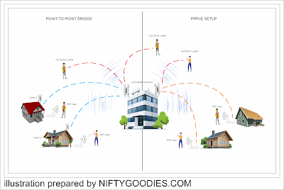
A Point-to-Point wireless ethernet bridge connection enables users to connect two or more locations that can share files, internet and other types of data across the network. This method is pretty much descent, eliminating the use of network cables from one point to the other and by other means it lowers the cost of your networking setup.
There are several CPE (customer premises equipment) wireless bridge antennas that comes with different features. CPE by definition refers to any piece of connected equipment that is used for accessing the Internet or generally accessing services on a provider network, whether directly or indirectly connected to that network.
As for this setup, we use COMFAST CF-E314N 300Mbps 2.4Ghz Outdoor Mini Wireless AP Bridge WIFI CPE Access Point Dual 2*14dBi WI-FI Antenna Nano station.
REQUIREMENTS
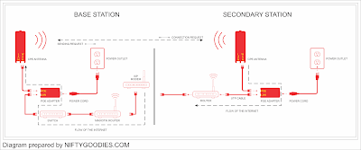
1. ISP MODEM to MIKROTIK ROUTER - Connect one end of your LAN cable from your ISP MODEM LAN 1 and the other end to your MIKROTIK ROUTER internet port or POE IN port.
2. MIKROTIK ROUTER to SWITCH - Connect one end of your LAN cable from your MIKROTIK ROUTER LAN 1 port and the other end to Port 1 of your switch.
3. SWITCH to POE ADAPTER LAN PORT - Connect one end of your LAN cable from your SWITCH port 2 and the other end to your POE ADAPTER Lan port.
4. POE ADAPATER to CPE ANTENNA - Connect one end of your LAN cable from the POE port of your POE ADAPATER and the other end to your CPE ANTENNA WAN port.
1. ROUTER to POE ADAPATER - Connect one end of your LAN cable to WAN port of your ROUTER and the other end into the LAN port of your POE ADAPTER.
2. POE ADAPTER to CPE ANTENNA - Connect one end of your LAN cable to POE port of your POE ADAPTER and the other end into the WAN port of your CPE ANTENNA.
3. ROUTER to LAPTOP / PC - Connect one end of your LAN cable to LAN 1 of your ROUTER and the other end into your LAPTOP / PC.
a. Plug the power cable to POE power supply.
b. Plug one end of your FTP cable to POE port of the power adapter. make sure that you have inserted it in the POE slot.
c. Plug the other end of your FTP cable to your CF-314N WAN port. make sure its in WAN not LAN.
A. Connect to CF-314N SSID using your mobile phone / laptop
B. Open Google chrome or any browser that is available to you and type 192.168.10.1
C. Enter default password (admin) or provide your desired password in your first login.
A. LOGIN TO COMFAST CF-314N Configuration page and create your password
B.WIZARD TAB
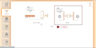
1. Click on the Wizard tab
2. Select Bridge
3.Select Station
4.Select Secondary site
5.Create IP Address (If this is your 6th antenna write 192.168.10.6) at the end for you to easily identify the assigned IP address of the antenna, if you have multiple antennas.
6. Click Next
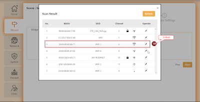
7. Click Scan
11. Create local SSID - make it descriptive so your clients can identify it right away.
12. Click Finish - you will see a confirmation page for the settings that you have made.


